MegaPulse Defib Surge P:

SKU: 00-MPDefib Surge P

Defib Surge Tester
EN 45502-1 Sec. 20 140V
External Defib Protection w/IGBTs

$6,250.00

Mains Voltage (leave blank for 120V)

Options

Defib Surge Tester <br />EN 45502-1 Sec. 20 140V <br />External Defib Protection w/IGBTs $6,250.00

Designed & Built in the USA

  • 1-Year Warranty
  • 100% Secure Checkout
Guaranteed Safe Checkout

The MegaPulse Defib Surge P is designed to conduct the test shown in EN 45502-1:1997 Para. 20.2, “Protection of the device from damage caused by external defibrillators”.  In accordance with this Standard reference, the Defib Surge P is built to the schematic shown in EN 45502-1 Figure 1 using the circuit values shown in Para. 20.2.

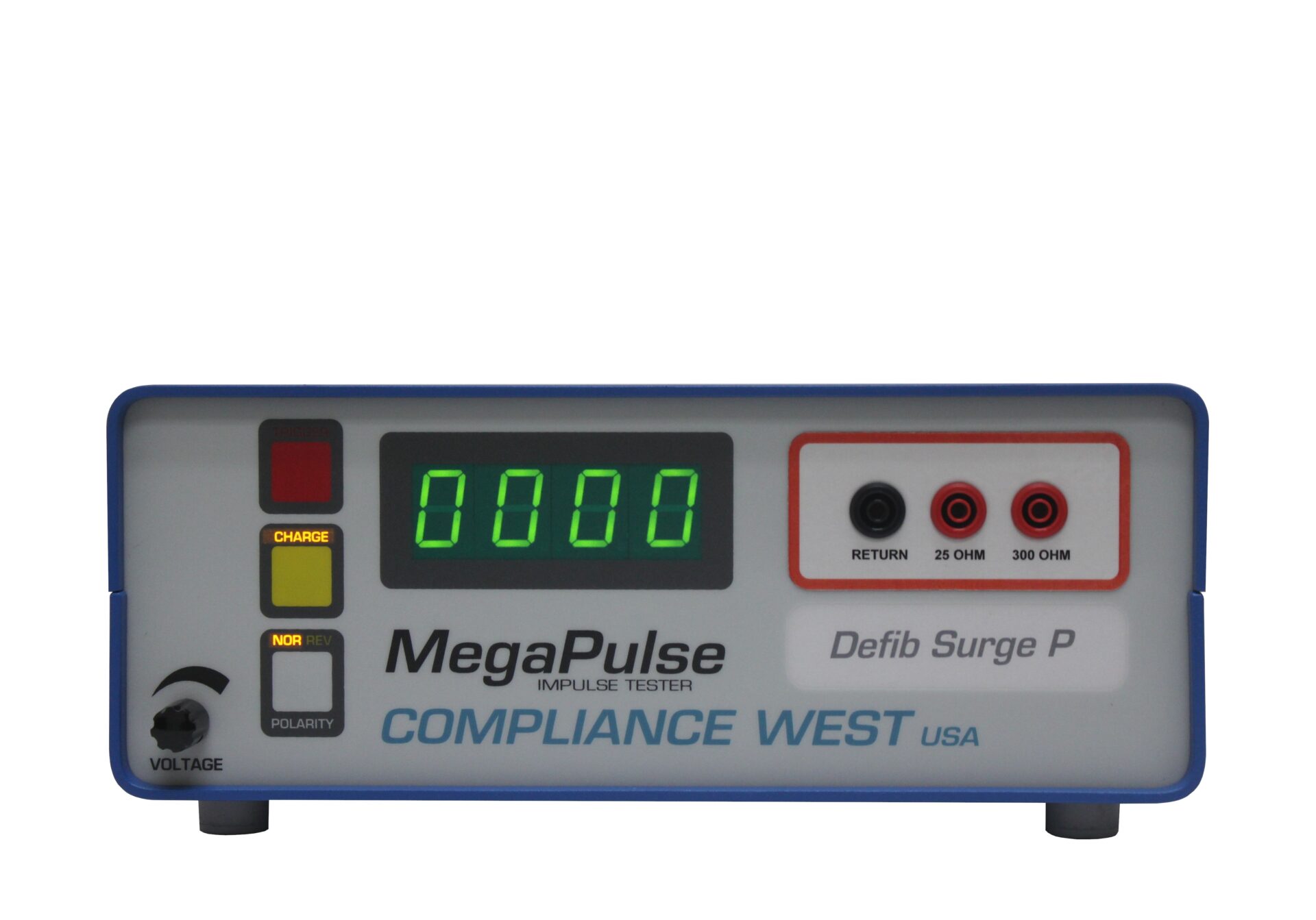
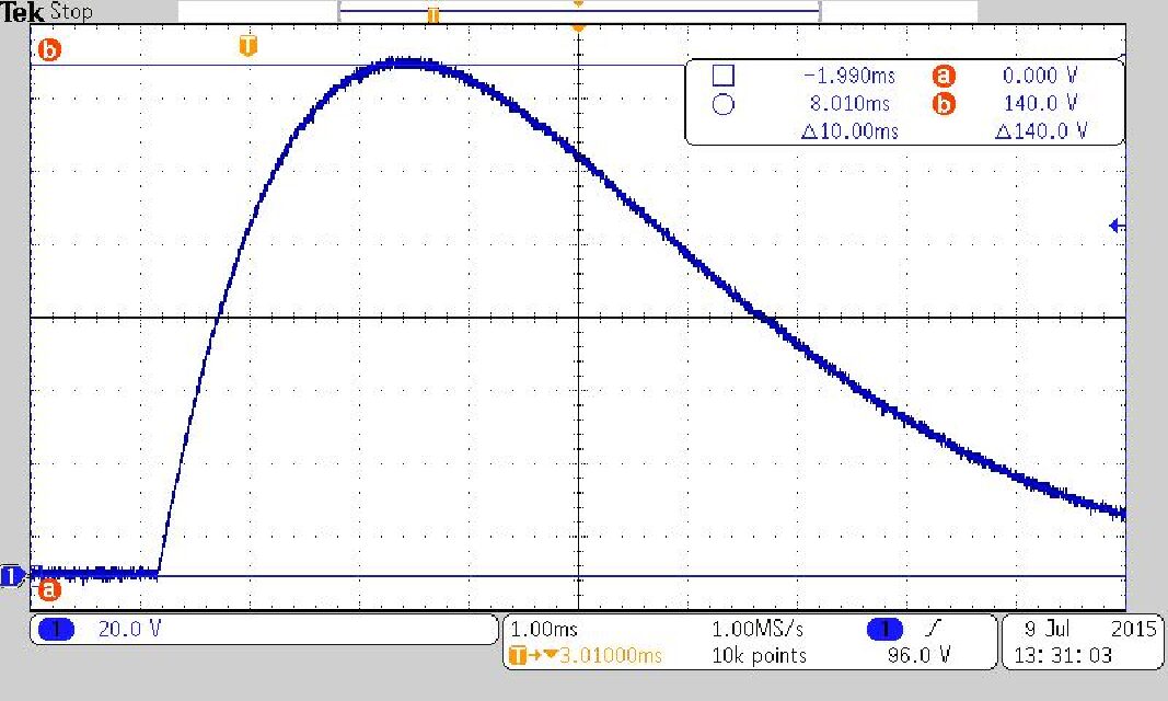
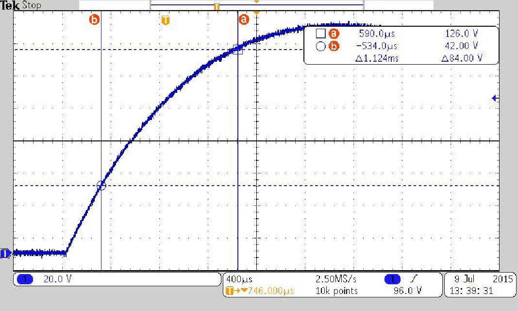
The output of the Defib Surge P is fixed at 140 volts peak, measured from the 10 ohm tap on the front panel, in accordance with the Standard.

A front-panel switch reverses the output polarity which is required for proper testing.

The output of the Defib Surge P can be measured with an oscilloscope using an appropriate 10X probe. (There is no BNC oscilloscope output on the Defib Surge P.)

The 300 ohm tap on the front panel is used to connect the AIMD to the Defib Surge P. The MegaPulse Defib Surge P uses IGBT switches to deliver a clean signal output.

The Tests contemplated in EN 45502 require 3 positive going pulses separated by 20 seconds; then after a 60 second pause, three negative going pulses separated by 20 seconds. The positive and negative pulses can be delivered manually using the front panel buttons, or the pulses can be set to operate under USB computer control using the TestMinder Megapulse option.

All pulses are delivered to the AIMD from the 300 ohm tap.

Options include 240V input voltage, a PLC Interface Relay Board and computer control via USB TestMinder MegaPulse.

The MegaPulse Defib Surge P ships with cables, graphs of theoretical and actual waveforms, and a Calibration Certificate. One-year warranty.

Features

• Up to 140V test Voltage.
• Microcontroller technologies.
• The front panel meter indicates test peak voltage at open circuit and polarity.
• Polarity button selector on the front panel.
• Manually operated Output Voltage knob.
• External interlock disables HV output and defeats test when circuit is open.
• Optional USB TestMinder, computer control with Auto-trigger via USB.
• Front panel switches and instructions for various test setups.
• Leads, manual and calibration certificate included.
• One year calibration cycle
• One year warranty.


Specifications

TESTING CIRCUITRY
Max Output Voltage: 140V tolerance -0V, +7V.
Rise Time (Tp): 1.5mS ≤ Tp ≥ 2.5mS.
Duration (Tw50): 3mS ≤ Tw50 ≥5.5mS.
Source Impedance: <10Ω.
Output Impedance: 300Ω ±15Ω, additional 25Ω port to measure Vtest.
Voltage Control: Manually, by turning a knob in the front panel.
Polarity Control: Positive and Negative. Optional control via USB TestMinder.
Voltage Display: 4 Digit LED Display.
Voltage Meter Accuracy: ±2V.
Duty Cycle: 1 pulse every 20 seconds.

ELECTRICAL
Line Voltage: 120V AC, 50/60Hz. Optional 220, 230 and 240V.

SAFETY
Safety Interlock Optional 2-pin terminal block on rear panel; shorted for operation.

OUTPUTS – FRONT
300Ω, 25Ω: High Voltage insulated rigid 4mm socket – Red.
RETURN: High Voltage insulated rigid 4mm socket – Black.

OUTPUTS – REAR
TESTMNINDER: DB9 Female (optional).
Inlet Module: Inlet module with fuse and power switch combination.