MegaPulse D8-PF:

SKU: 00-MPD8-PF

Defib-proof and Energy Reduction Tester
5000V 360J

Call for Price

Surge Tester for IEC 60601, IEC 80601, EC-13, EC-53.

Designed & Built in the USA

  • 1-Year Warranty
  • 100% Secure Checkout
Guaranteed Safe Checkout

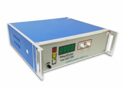
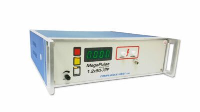
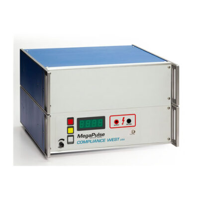
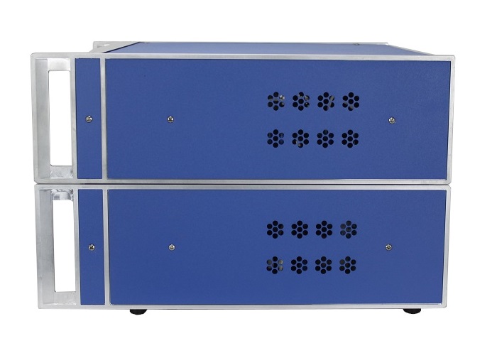
The most advanced medical surge tester available, the MegaPulse D8-PF is the latest iteration of the industry leading Defib-proof Tester from Compliance West.  It adds the new Differential Mode Test shown in IEC 80601-2-26 and introduces our new touch controlled front panel to the legendary MegaPulse D5-PF defib proof tester.  The MegaPulse D8-PF retains the direct energy readout and comprehensive list of included tests to the requirements of:

  • IEC 80601-2-26:2019/COR1:2021 Figure 201.101 Defibrillation-Proof Applied Parts (S/N 435193 and up).
  • IEC 60601-1:2005 (Issue 3) Figure 9 and 10 Defib-proof Differential- and Common-Mode Test  (IEC 60601-1 Figure 50 in older versions).
  • IEC 60601-1:2006 Figure 11 Energy Reduction Test.
  • IEC 60601-2-4: 2010 Figure 201.110 Overload Test (optional).
  • IEC 60601-2-34 Issue 2 (optional).
  • IEC 60601-2-34 Issue 3 (included).
  • IEC 60601-2-49.
  • EC-13.
  • EC-53.
  • IEC 60601-2-25:2011.
  • IEC 60601-2-27:2011.

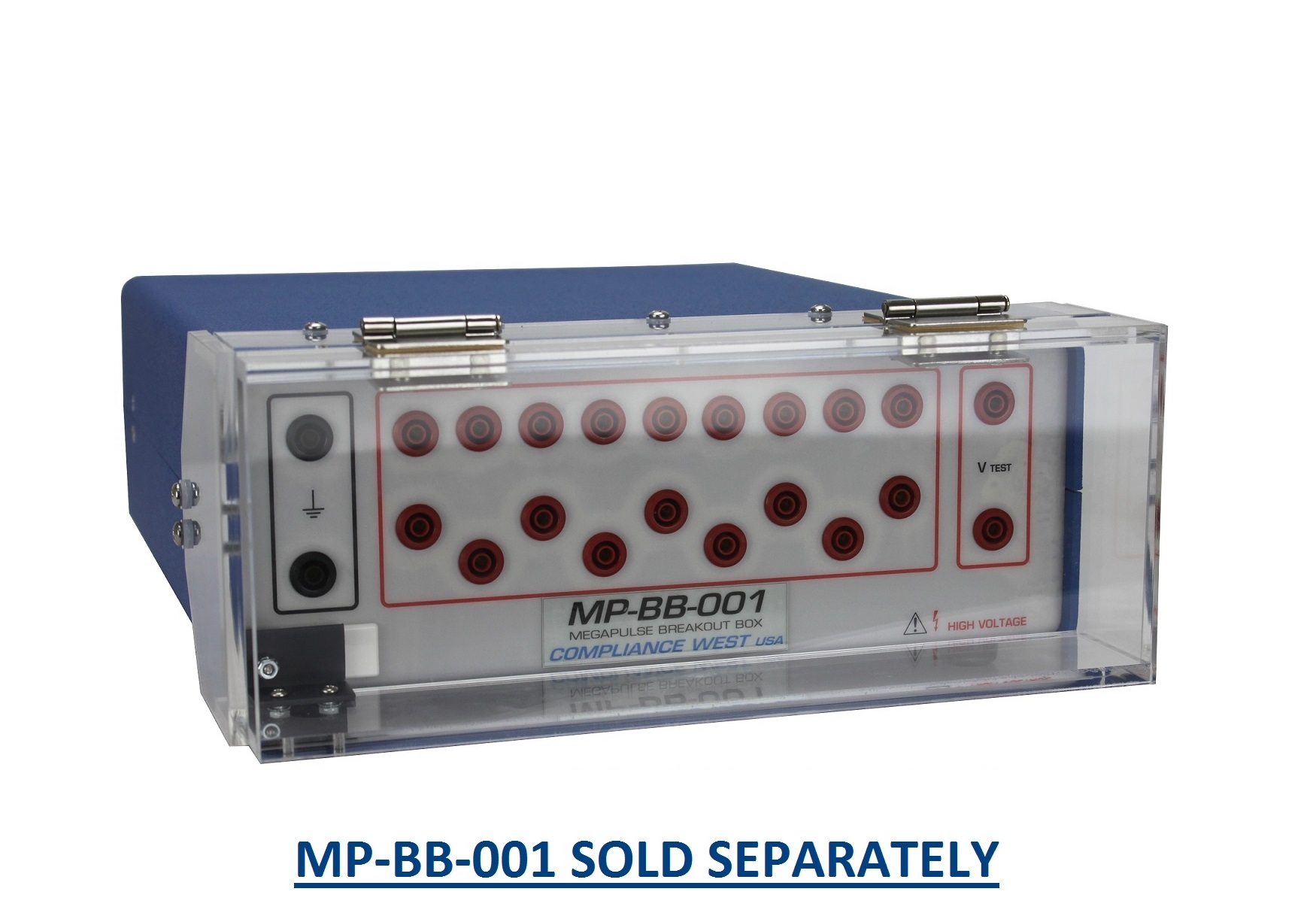
This is an IEC 60601 and IEC 80601 Defibrillation-proof tester.  For the Energy Reduction test, joules consumed in the 100Ω resistor are immediately displayed after each pulse. The MegaPulse D8-PF tests protection against the effects of defibrillation (Common Mode, Differential Mode) and Energy reduction test (EC-13) and as noted in the Standards shown above. The MegaPulse D8-PF outputs a 360J Defib-proof test pulse per IEC 60601-1 for the Energy Reduction Test.  It can also be used as a Defibrillator Lead Tester.

Features

  • Updated front panel with digital switches.
  • Digital output voltage knob on the front panel.
  • Integrated High Voltage on hold circuit.
  • Integrated Energy measurement.
  • Joules readout for the last pulse is displayed by pressing a button.
  • Integrated Y1-Y2 measuring circuit.
  • Built-in Pass/Fail reference circuit.
  • External interlock disables HV output and defeats test when circuit is open.
  • Long life capacitor rated for 2.5 million pulses.
  • USB TestMinder, computer control.
  • Auto-trigger via USB.
  • Front panel indicates internal HV and polarity.
  • Polarity button selector on the front panel.
  • Front panel switches and instructions for various test setups.
  • Microcontroller technologies.
  • Leads, manual and calibration certificate included.
  • One year calibration cycle.

Specifications

TESTING CIRCUITRY
Charge Voltage: 5100V ±1%.
Main Capacitance: 32uF ±5%.
Inductances: 500uH and 25mH ±5%.
Main Resistance (R1): 100Ω ±1% non-inductive.
Output Impedance: 50Ω and 400Ω ±1% non-inductive. Optional 10Ω available.
Voltage Control: Manually, by turning a knob in the front panel or via USB.
Polarity Control: Positive and Negative. Alternating control available with USB.
Voltage Display: 4 Digit LED Display.
Voltage Meter resolution: 5V.
Voltage Meter Accuracy: ±1%.
Duty Cycle: 20s between pulses, ±1% 100Ω resistor bank, up to 70 pulses.
12s between pulses, +1% <-5% 100Ω resistor bank, continuous duty

ENERGY MEASUREMENT
Works only when: 25mH inductor selected (in accordance with the energy reduction test).
Display Resolution: 1 Joule.
Repeatability: ± 2 Joules between pulses.
Reading: From 3000V to 5100V only.

ELECTRICAL
Line Voltage: 120V AC, 50/60Hz.
230V AC ±10%, 50 Hz ±1 Hz (CE for EU).

SAFETY
Safety Interlock 2-pin terminal block on rear panel; shorted for operation.

OUTPUTS – FRONT
50Ω, 400Ω, AUX, MEAS. POINT: High Voltage insulated rigid 4mm socket – Red.
RETURN: High Voltage insulated rigid 4mm socket – Black.
Y1, Y2, SINE WAVE: BNC.

OUTPUTS – REAR
ENERGY MEASUREMENT: High Voltage insulated rigid 4mm socket – Red.
GROUND: High Voltage insulated rigid 4mm socket – Black.
TESTMNINDER: DB9 Female.
Inlet Module: Inlet module with fuse and power switch combination.

Documents

Detailed Information about the MegaPulse D8-PF

White Paper – Oscilloscope Setup to Capture Y1-Y2 waveform in accordance with Iss. 3 Fig. 10

Listen to Expert Highlights